Everything on top of the conveyor set the ceiling
The conveyor fed into the trailer from the rear, so the tallest thing on it decided how far in it could go. With the motor, gearbox and mounting beam riding the upper deck, the assembly bottomed out against the trailer roof well short of the nose.
Product piled up near the door and the front of the trailer stayed empty. The operation was paying full freight to move partly full boxes.
Whatever solved it had to clear the roof without rebuilding the conveyor or changing how it was fed.
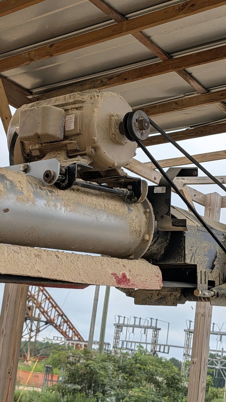
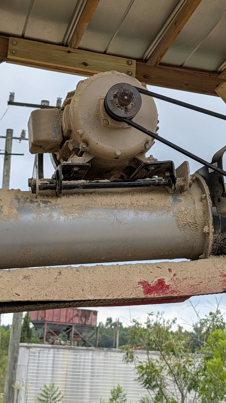
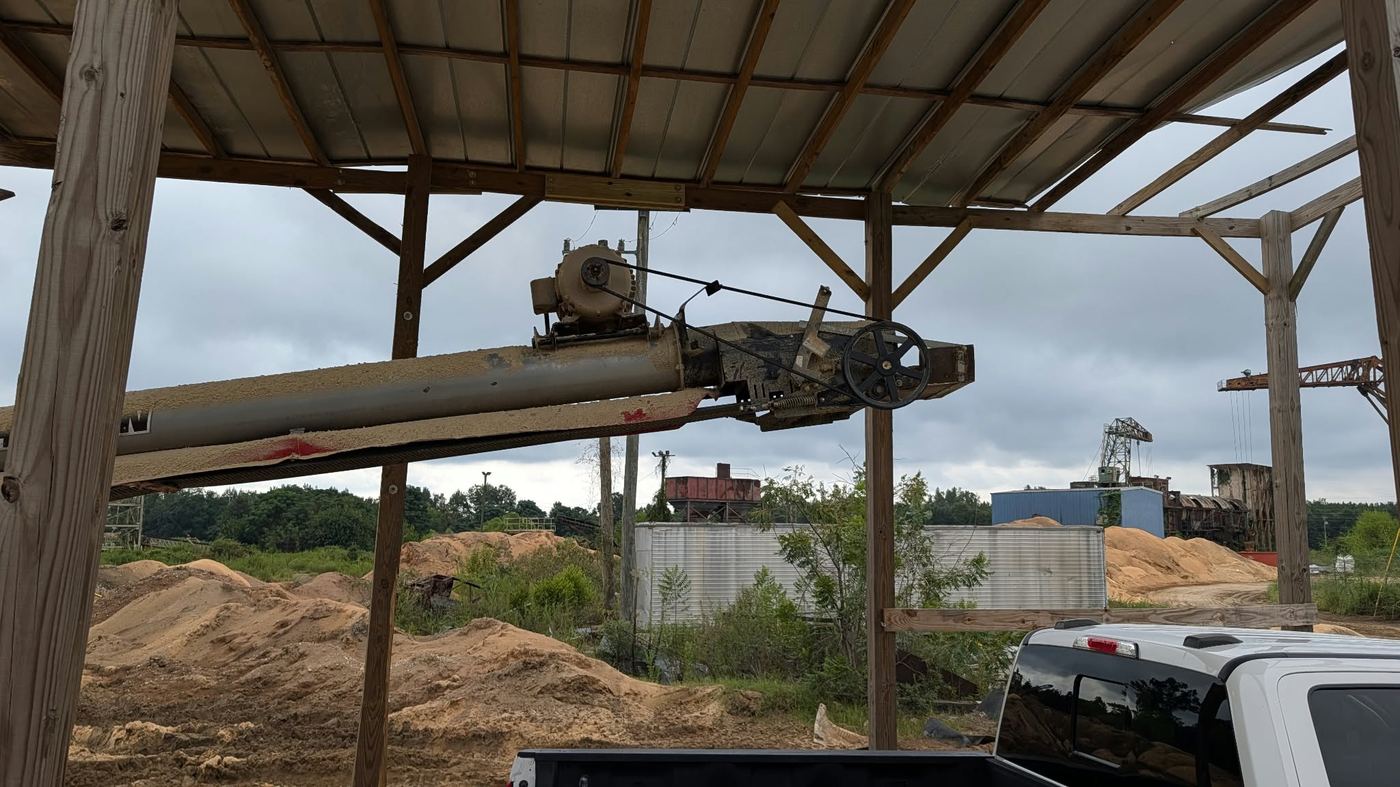
Move the drive underneath
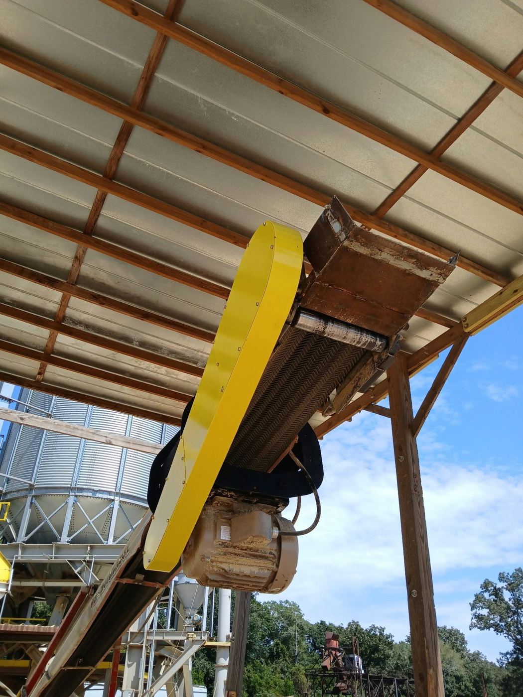
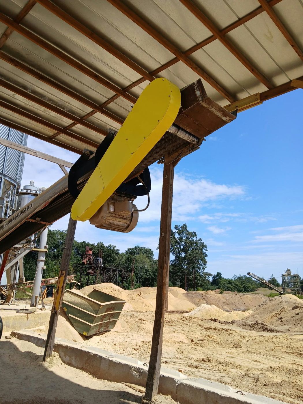
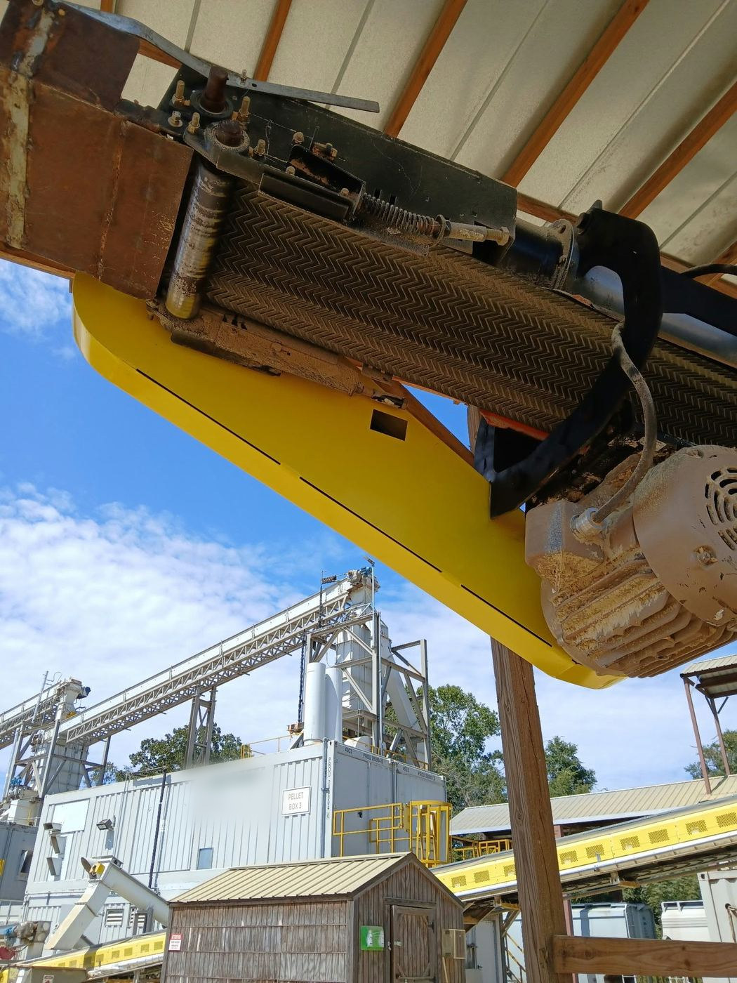
Relocating the motor, gearbox and belt drive to the underside cleared the top deck completely. The conveyor now runs deep enough into the trailer to fill the box.
The relocation needed new saddle brackets to carry the motor in its new position, a mounting for the drive, and standoffs tying it all back to the existing frame. Everything was designed around the conveyor as it already stood. Nothing on the original machine was replaced.
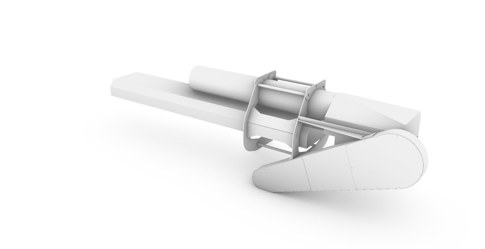
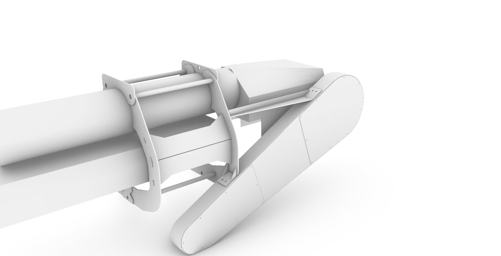
The fix created a hazard, so the fix included the guard
Overhead, the open drive was out of reach. Underneath, the sheaves, belt and motor sit at walk-by height in a spot people pass on foot. That is a contact and pinch exposure that did not exist before the change.
The guard was drawn, nested and cut in the same package as the relocation hardware. It was not a follow-up job after somebody raised it.
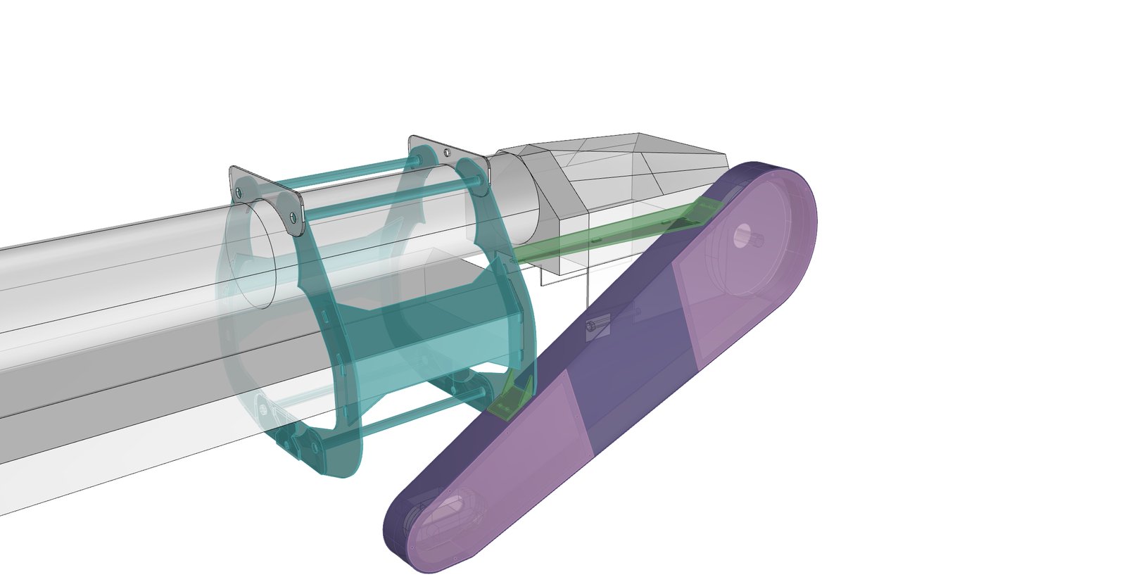
Built so it can only go together one way
No rework was part of the brief, not a hope. Somebody else was going to cut these parts and somebody else was going to weld them, without me standing there, and whatever came off the table had to fit the machine the first time. That requirement is what shaped the weldment.
Every plate-to-plate joint in it is a tab passing through a slot. Parts self-locate and self-square against each other. Gusset feet are stepped asymmetrically, so each one seats in a single orientation and the assembly physically cannot be built wrong.
The tabs run all the way through rather than butting against a face. That gives weld access on both sides of the joint and a seat check anyone can confirm by eye from outside the assembly. A butt joint hides a bad fit until it cracks.
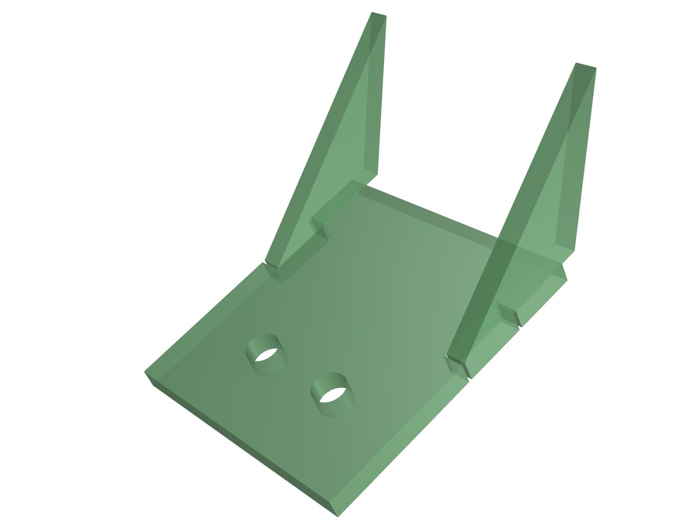
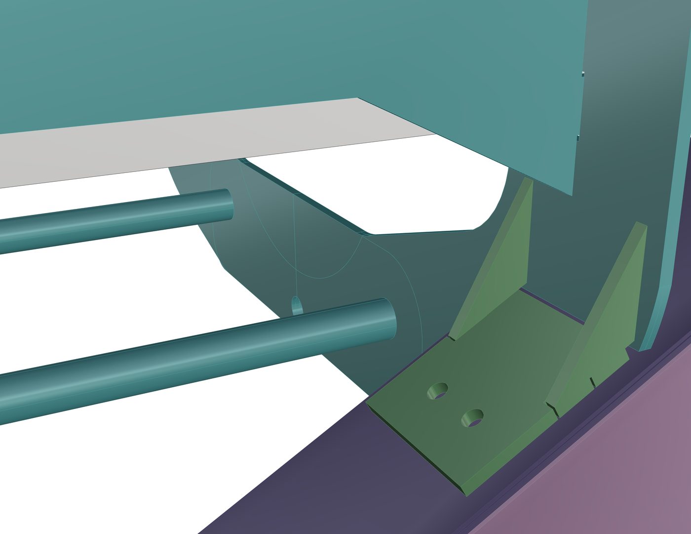
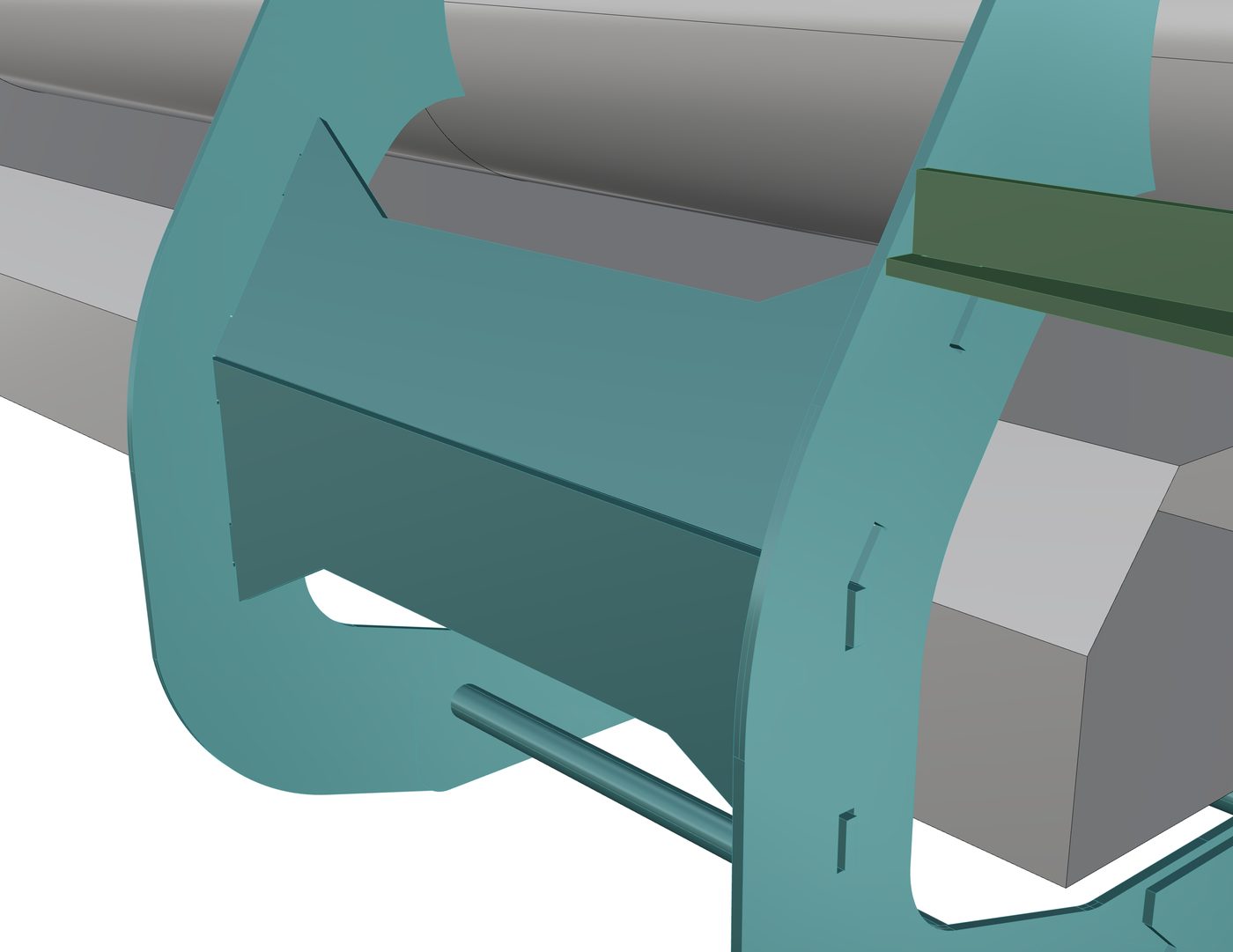
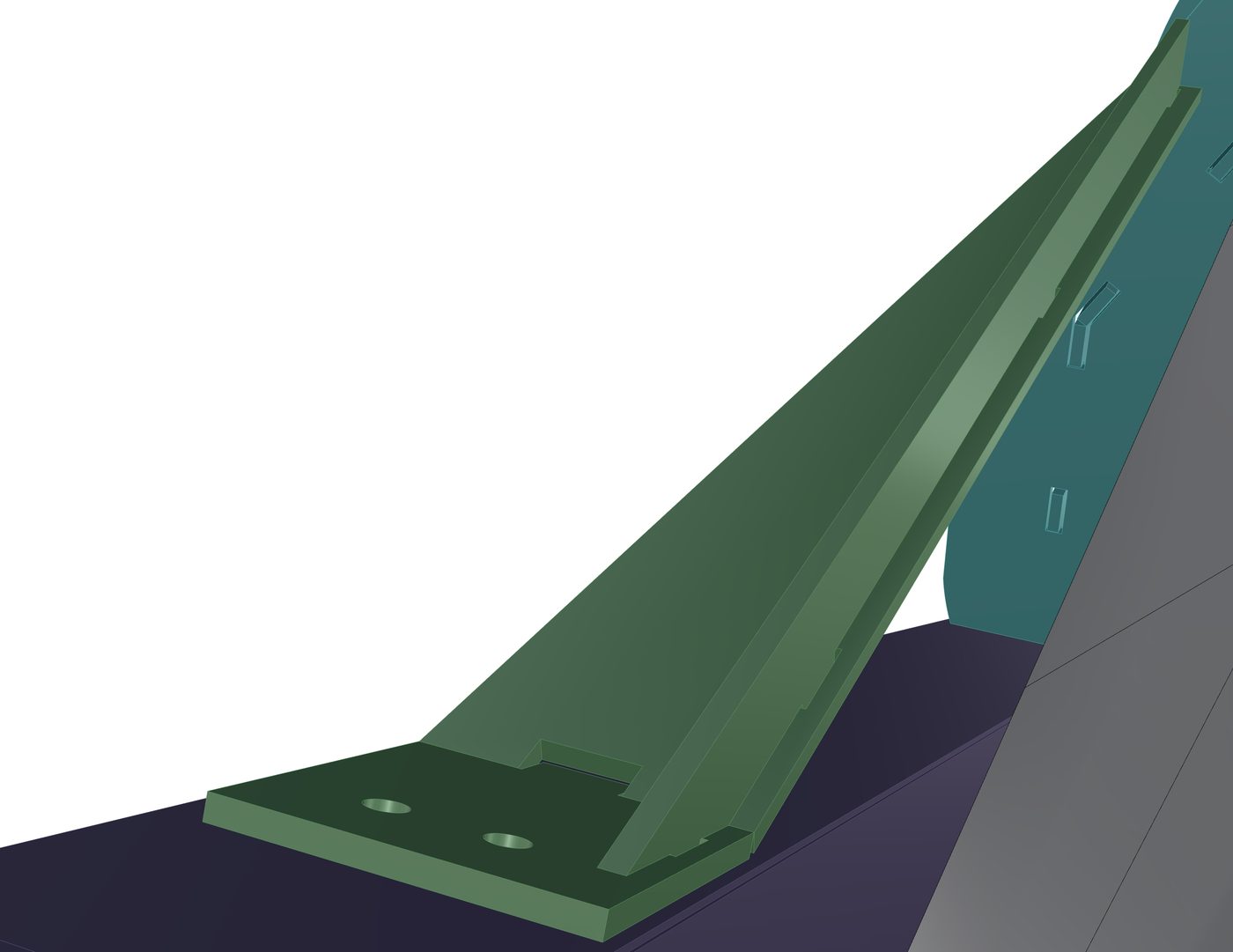
On a waterjet the notch is part of the same cut path as the outline, so the feature adds no material and no setup. What it removes is fit-up labor, which is the slow, variable, skill-dependent part of building a weldment. Cutting is the cheap and predictable part.
Nested to stock the shop already buys
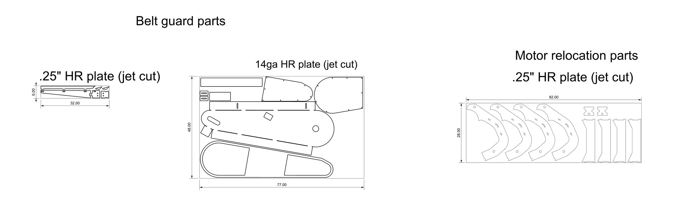
Parts were grouped by material and thickness and nested onto real blank sizes. Structural brackets and motor saddles in quarter-inch hot-rolled plate, guard shell in 14 gauge.
This package belongs to the customer. It goes to any fabricator as a complete, build-ready set, so bids come back against a known quantity instead of each shop having to design its own version before it can price anything.
In service
The conveyor reaches the front of the trailer. The drive is enclosed. The plant loads 20 to 30 percent more material into every box that leaves the yard.
- Client
- Industrial Manufacturing · Albany, GA
- Site
- Pellet production plant
- Engagement
- On-site assessment through release to fabrication
- Role
- Design only · fabrication and installation by others
- Requirement
- Fit and install first time, no rework
- Scope
- Drive relocation, motor mounting, belt guard
- Problem
- Top-mounted drive fouled trailer roof, limiting load
- Result
- 20–30% more material loaded per trailer
- Materials
- .25" HR plate, 14ga HR plate
- Stock
- 6×32, 28×82 (.25") · 48×77 (14ga)
- Cut process
- Waterjet
- Assembly
- Tab-and-slot, no fixture required
- Software
- Rhino 3D
- Delivered
- 3D model, cut files, nest layouts
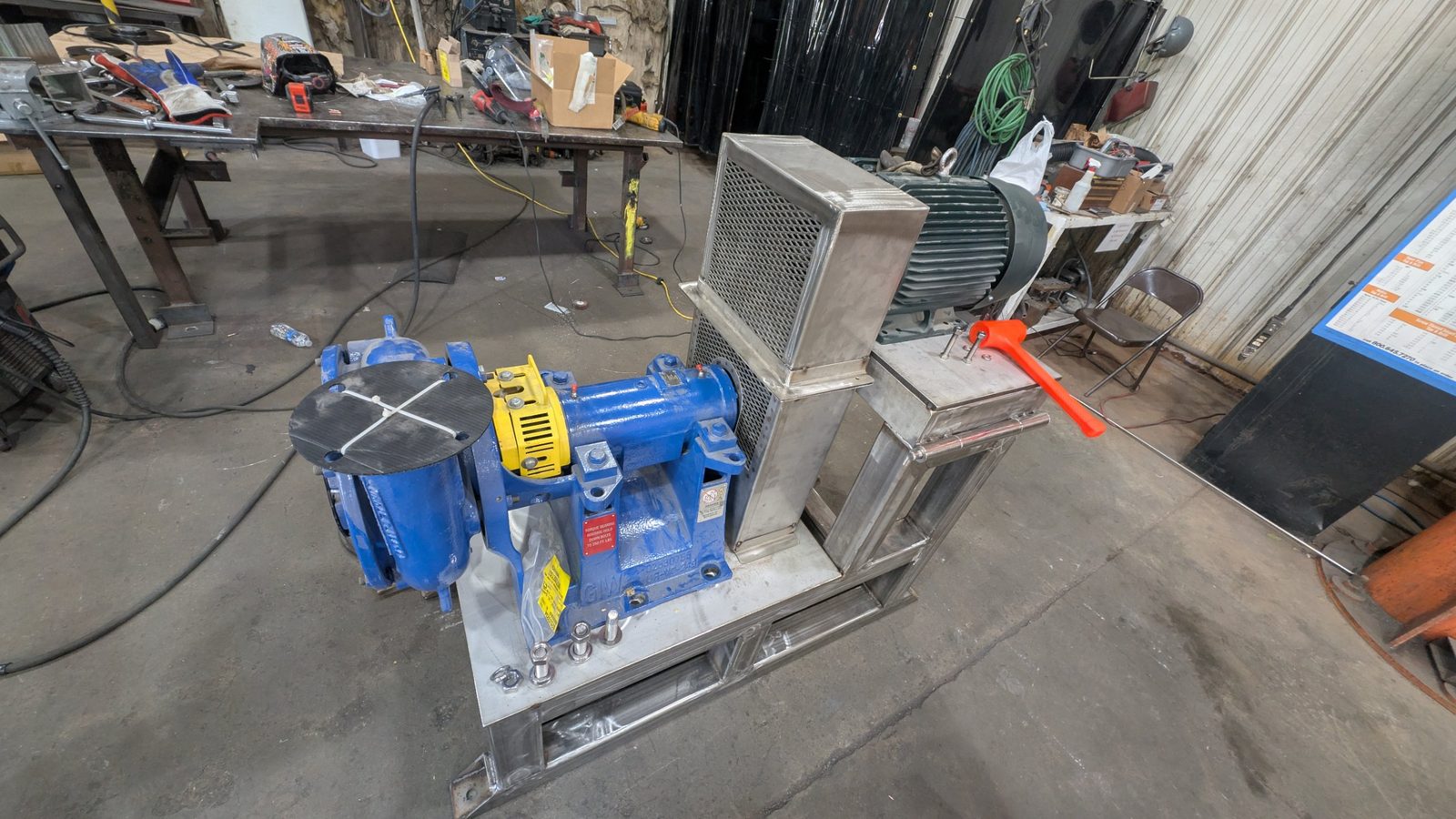
A pump stand that comes apart in the right order
Pulp mill pump stand
The stand it replaced was rusting out, and the motor sat directly over the pump so it had to come off first for any pump work. The replacement splits the two onto their own decks.
Got something like this?
A phone call and a few photos is usually enough for me to tell you whether it's something I can help with.