Twenty years of it
Equipment, structures, fixtures and parts — drawn to be built, and a fair few of them shown drawn and then built. Two are written up in full; the rest are here because they speak for themselves.
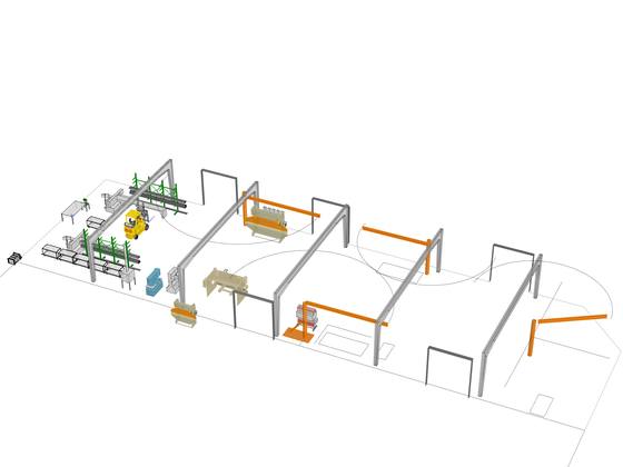
Fabrication shop layoutMachines, crane coverage, racking and material flow laid out before anything got moved.
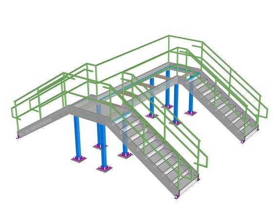
Crossover stair and platformStair, landing and guardrail over a process line. Colour by assembly so the shop can see what ships together.
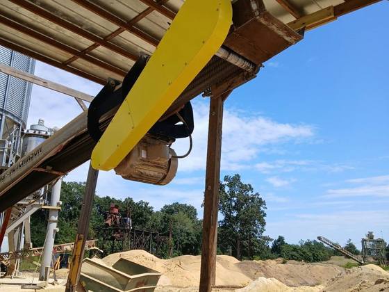
Conveyor drive relocationDrive moved underneath so the belt could reach the nose of the trailer. Guard designed in the same package.Case study →
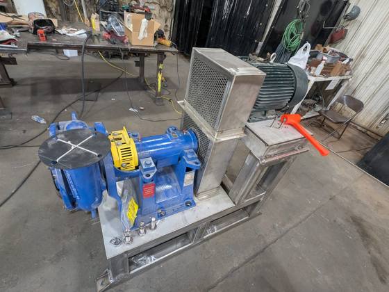
Pulp mill pump standStainless, split level, so the pump lifts out without the motor moving.Case study →
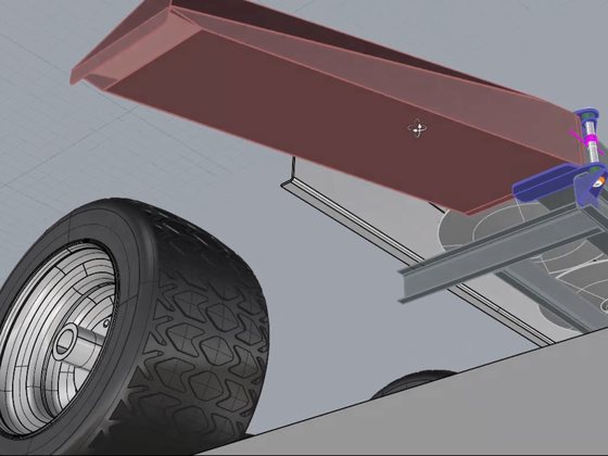
Stainless chute, drawn onto the machineModelled against the machine it had to mount to, so the hinge line and the swing were settled before anything was cut.
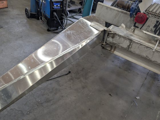
…and the same chute, builtLong folds, welded corners, nothing bolted through the face of it.
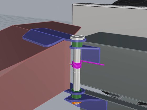
The hinge, worked out firstPin, bushings and brackets drawn as an assembly. None of this gets sorted out at the table with a tape measure.
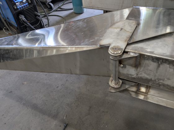
…and the hinge in stainlessWhat came off that drawing. Same pin, same bracket, welded to the chute wall.
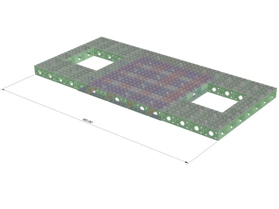
Modular fixture tableWelding table built in sections, perforated for clamping, so it goes together to whatever size the bay allows.
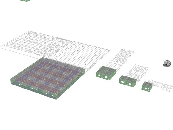
…and every part that makes itSame table, pulled apart, with the flat patterns laid out beside it. This is the half of the job the shop actually gets.
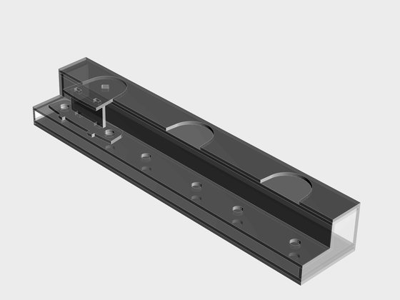
A bearing bracket, and the jig that welds itI drew the bracket, then drew the fixture that holds three of them at the right angle while they get welded.
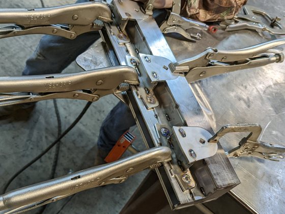
Three located at onceThe jig does the measuring. Every bracket lands at the same angle whether it is the first one or the thirtieth.
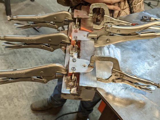
…and welded on the railStraight down the fixture, one after another, with copper behind the joint. The third one comes off matching the first.
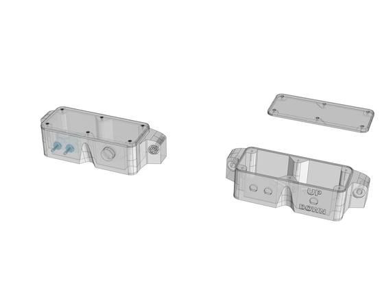
Sealed control enclosureTwo-button station with a sealed connector and moulded legends. Printed rather than machined.
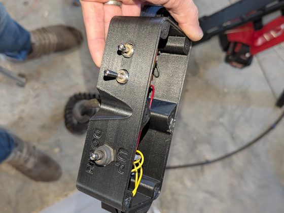
The same enclosure, printedLegends moulded into the body rather than stuck on, so there is no label to peel off in the weather.
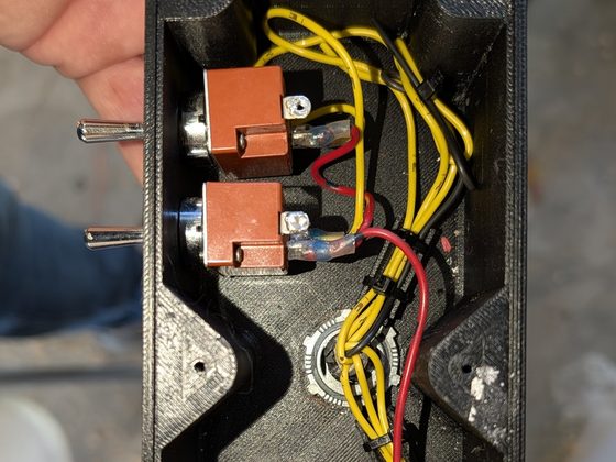
…and the inside of itRibs locate each switch and give the loom somewhere to sit. Designed around the wiring, not just around the buttons.
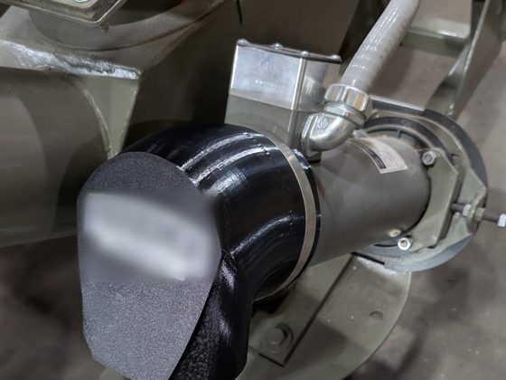
Motor snorkel, printed in TPURain was getting into the motor ports. TPU flexes under the clamp instead of cracking the way a rigid print would.
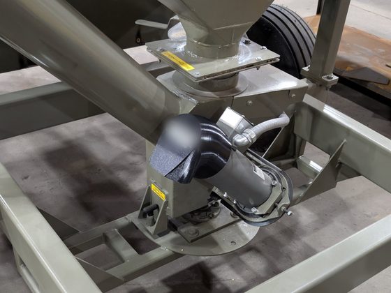
…in service, outdoorsOn a machine that lives outside. Printing was the right answer for this part, not the default one.
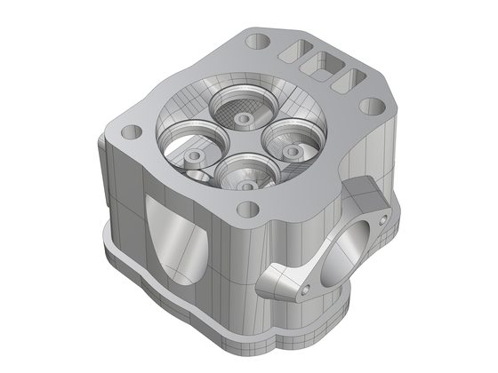
Four-valve cylinder headChamber, seats and port runs for a prototype engine. Machined-part work, a long way from plate and tube.
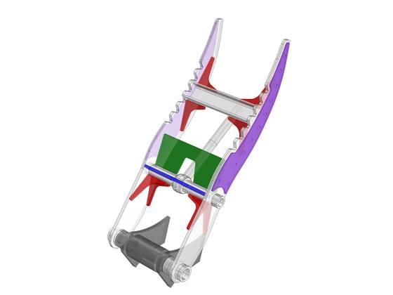
Mini excavator thumbHydraulic thumb and mount, built around the machine it had to bolt to.
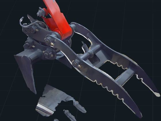
…and the scan behind itNo drawings exist for most machines. Scanning the arm is how the mount above was made to fit the first time.
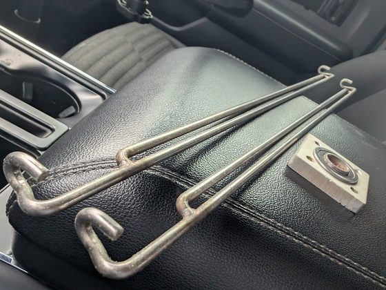
The conveyor rod nobody could sourceDrawn from the one sample left on the belt and had made. When the genuine part finally turned up it cost three times as much.
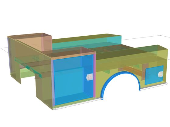
Truck service bodyCompartments, doors and latch hardware solved as one assembly before any sheet got bent.
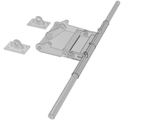
Grab arm and mountingLinkage, cylinder and bearing mounts for a machine already in service.
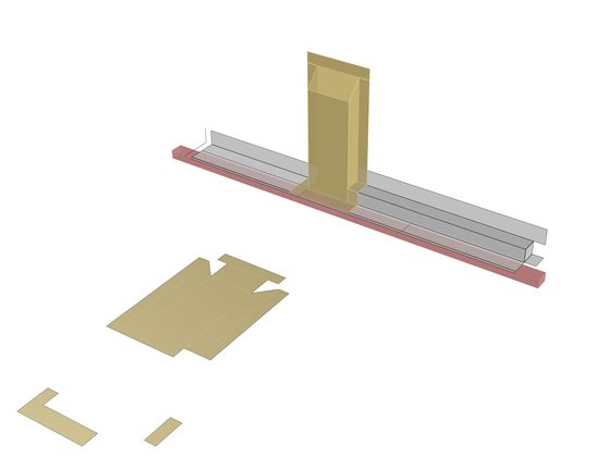
Custom-fit flashingTrim folded to match what was already standing, with the flat patterns to brake it from.
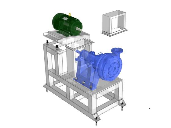
Designed to come apartGuard, motor and pump each clear the frame on their own. Nothing is trapped under anything.
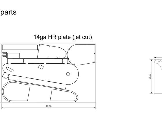
Nested to real stockParts grouped by material and thickness on blank sizes the shop already buys.
Most of what I do looks nothing like the last one
Twenty years of it has covered equipment, structures, guarding, fixtures, replacement parts and whole shop layouts. If what you need isn’t on this page, that’s normal — call and describe it.